
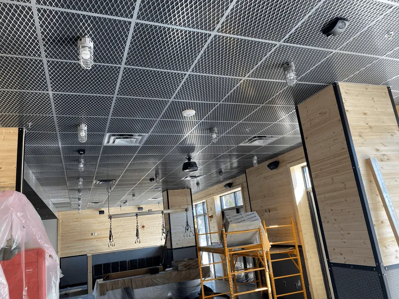
Once gypsum panels, FRP, ceiling tile, or another finish conceals an assembly, a project team may struggle to locate backing, distinguish one penetration from another, confirm which revision was installed, or explain why a soffit or access point moved. Random phone photos are better than no record, but they become difficult to use when filenames, locations, orientations, and drawing references are missing.
This index is a documentation pattern, not an inspection, code determination, firestop record, warranty, or substitute for approved documents. The project architect, engineer, authority, commissioning team, manufacturers, and responsible trades determine what must be installed, inspected, tested, and approved.
Create the location system before taking photos
Use the project's existing identifiers whenever possible: building, floor, grid line, room number, wall type, ceiling type, elevation, and drawing revision. Add a directional convention such as “viewing north” or “east elevation.” If the plans do not identify a useful field location, ask the project team to approve a zone map instead of inventing labels independently.
Place a readable ID board in the first image for each sequence. It should show project, floor, room or zone, elevation or view direction, date, stage, photographer, and current drawing revision. The board lets an exported image retain context even when separated from the folder.
Use the same nine stations in every room or zone
- Orientation: wide view from the entry or approved zone origin.
- Partition base: track, slab interface, openings, and nearby embedded or under-slab constraints visible at that stage.
- Partition head: head-of-wall, deck, deflection, bracing, or other specified condition before concealment.
- Backing: each backing type with dimensions from stable references and the fixture, casework, equipment, rail, or accessory it supports.
- Rough-ins: coordinated mechanical, electrical, plumbing, fire-protection, low-voltage, and controls work visible in or above the assembly.
- Penetrations and joints: one context view and one labeled close view; keep the responsible trade's approved inspection or system record separate but linked.
- Ceiling interfaces: soffits, perimeter conditions, clouds, elevation changes, access panels, grid edges, and suspension conflicts.
- Device layout: lights, diffusers, sprinklers, speakers, sensors, signs, cameras, access points, and other ceiling devices against the reflected-ceiling plan.
- Close-in panorama: final clockwise sweep after corrections and before the specified concealment release.
Name every image for retrieval
A practical filename pattern is project-floor-room-elevation-subject-date-sequence. Example: oak-02-214-east-backing-2026-08-11-03.jpg. Avoid relying on GPS or automatic timestamps; indoor location can be inaccurate and exported files may lose metadata.
Keep a simple index with these columns:
- Photo or sequence ID and file path
- Building, floor, room or zone, grid, elevation, and view direction
- Subject and responsible scope
- Drawing, detail, submittal, RFI, or change reference with revision
- Date, photographer, stage, and work status
- Open issue, responsible party, due date, and linked closeout photo
- Inspection or release reference when required by the project
Photograph decisions, not just materials
| Condition | Context to preserve | Linked record |
|---|---|---|
| Backing | Room elevation, backing material, vertical and horizontal dimensions, framing relationship, and intended supported item | Approved backing detail, equipment or accessory submittal, and layout approval |
| Partition change | Original and revised layout, endpoints, affected openings, ceiling relationship, and adjacent trade work | RFI, sketch, bulletin, approved change, and revision distributed to trades |
| Penetration | Assembly context, opening or sleeve, penetrating item, annular condition, and final visible state | Responsible trade's listed system, inspection, testing, or quality record as required |
| Ceiling conflict | Grid/module, elevation, device centers, access requirement, obstruction, and proposed relocation | Coordinated reflected-ceiling plan, approved field decision, and affected submittals |
| Access point | Panel type and size, service target above, clearance, finish relationship, and unobstructed opening | Approved access schedule and maintenance or commissioning requirement |
Separate documentation from acceptance
A photograph can show what was visible from one angle at one time. It cannot establish material hidden behind the view, confirm an entire listed assembly, replace measurements or tests required by the project, or prove that an authority accepted the work. The index should therefore link to the actual inspection, testing, submittal, or release record rather than labeling a picture “passed.”
Likewise, a field photo should not become an unofficial design revision. When work differs from the current documents, open a question, identify the responsible decision-maker, and attach the approved response. Then photograph the corrected or approved condition under a new sequence without deleting the earlier record.
Coordinate ceilings before the grid hides the problem
Reflected-ceiling plans and named ceiling-system instructions govern project-specific layout and installation. A useful coordination photo shows perimeter conditions, elevation, hanger and support context, obstructions, access needs, and the relationship among devices. It should not be used to improvise structural support, bracing, seismic details, fire-resistance requirements, or manufacturer-specific installation.
For specialty systems, retain the current manufacturer documents for the exact product. Armstrong's commercial installation library, for example, organizes resources by suspension, panel, specialty, and integrated system. A generic screenshot from a different system should not substitute for the selected product's instructions.
Run a close-in gate by zone
- Current plans, specifications, approved submittals, RFIs, and changes identified
- Framing, backing, rough-ins, penetrations, insulation, and special assemblies complete for the released zone
- Trade conflicts and access requirements resolved in writing
- Required inspections, tests, or observations completed and referenced
- Nine-station photo sequence indexed and open issues linked
- Responsible project representative authorizes concealment for that specific zone and revision
Release smaller named zones instead of using one verbal approval for an entire floor. A zone register makes partial progress visible and reduces the chance that a correction in one room is mistaken for a building-wide decision.
Deliver a durable closeout package
Export the approved zone map, index, original-resolution images, view-only PDF contact sheets, issue register, and linked document references. Keep a README that explains the naming convention and known gaps. Confirm ownership, retention, privacy, security, and permitted use with the project team before recording occupied or sensitive areas.
The result is a practical retrieval method built around fixed stations, location-first filenames, decision links, correction pairs, and zone-level release. It turns a folder of jobsite images into a record that future owners, facility teams, designers, and contractors can navigate.
Primary reference points
- Hillsborough County commercial building plan-review requirements — examples of coordinated plan information reviewed by the local authority.
- Armstrong Ceiling Solutions commercial installation resources — product- and system-specific commercial ceiling references.
- Gypsum Association GA-225 repair tutorial — context for identifying and restoring fire-rated gypsum panel systems rather than treating them as generic surfaces.
Southern Drywall Services prepared this field index as a coordination aid for commercial and custom-residential interior projects. Approved project documents and the responsible design, inspection, and trade professionals control the work.